Introduction
Imagine this scenario: A CNC machine hums along on the production floor, cutting parts just like it has for months. The operator sees no warning lights, hears no unusual sounds, and the cycle times look normal. But when those parts reach inspection, they're rejected—dimensions are off by just enough to fail spec. The result? Costly rework, scrapped material, and a scramble to figure out what went wrong.
Measurement errors often go unnoticed until they become expensive problems. Precision measurement is the backbone of quality manufacturing — understanding it, and maintaining it, is what separates a predictable production line from one plagued by unexpected failures.
This article covers what precision measurement means, how it differs from accuracy, which tools verify machine performance, and why regular calibration is the thread holding it all together.
What Is Precision Measurement?
Precision measurement is the process of quantifying physical dimensions, properties, or quantities to a very high degree of exactness—going well beyond basic measurement to detect variations as small as millionths of an inch. According to the International Vocabulary of Metrology (VIM), precision is defined as the "closeness of agreement between indications or measured quantity values obtained by replicate measurements on the same or similar objects under specified conditions."
This level of exactness matters in modern manufacturing because tight tolerances in CNC machining, aerospace, electronics, and medical device production require measurements that a standard ruler or gauge simply cannot provide. Standard CNC prototype tolerances baseline at ±0.005 inches (127 µm), with precision tolerances reaching ±0.001 inches (25 µm) or tighter.
When your specifications demand this level of control, your measurement system must detect deviations far smaller than the tolerance zone itself.
Resolution vs. Tolerance: Understanding the Difference
Two concepts define whether your measurement system can actually do its job:
| Concept | What It Means |
|---|---|
| Resolution | The smallest increment an instrument can reliably detect. A laser interferometer at 1.0 ppm resolution catches changes as small as one millionth of an inch per inch. |
| Tolerance | The allowed variation on engineering drawings — the range your finished part must stay within to pass inspection. |
ISO 22514-7:2021 establishes that measurement system resolution should be ≤ 5% of the tolerance zone. If you're measuring a tolerance of ±0.001 inches (0.002 inches total), your measurement system should resolve to at least 0.0001 inches to provide reliable verification.
Precision Measurement as an Ongoing Practice
Precision measurement isn't a one-time event. Tools must be regularly verified against a known standard to ensure their readings remain trustworthy over time.
Even the most precise instruments drift due to wear, environmental exposure, and regular use. For manufacturers in Portland OR and SW Washington, Sarkinen Calibrating provides NIST-traceable calibration with accuracy to 1.0 parts per million — and local service means faster response times when your production schedule can't wait.
Accuracy vs. Precision: Understanding the Difference
These terms are often used interchangeably, but they describe fundamentally different measurement characteristics. Understanding the distinction is critical for maintaining quality in manufacturing operations.
Defining the Terms
Accuracy is how close a measurement is to the true or accepted value. An accurate measurement system produces results that match the actual dimension of the part being measured.
Precision is how consistently a measurement can be repeated. A set of measurements can be highly precise (tightly clustered) while still being far from the true value. Precision depends on the distribution of random errors, not systematic bias.
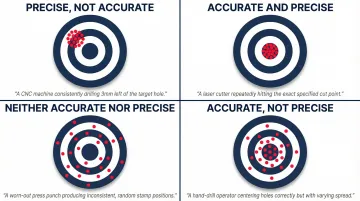
The Target Analogy
Picture a CNC drill making holes in a part. If every hole lands in exactly the same wrong spot, the process is precise but not accurate—the machine repeats consistently, but a systematic error (a fixture offset or spindle misalignment) is pulling all results in the wrong direction.
If holes scatter around the correct location, the process is accurate on average but not precise—the mean position is right, but random variation from operator technique, vibration, or tool wear puts each hole somewhere slightly different.
Manufacturing operations need both. Accuracy ensures parts meet specification; precision ensures every part off the line matches the last one. Neither compensates for the other.
Systematic vs. Random Errors
Systematic Error (Bias) remains constant or shifts in a predictable direction across repeated measurements. Common examples in a shop environment:
- A worn micrometer consistently reading 0.0005 inches high
- An uncalibrated CMM with a probe offset error
- Thermal expansion causing all measurements to drift in one direction
Systematic errors can often be corrected numerically once identified, but detecting them requires calibration against a known standard.
Random Error varies unpredictably between measurements and requires statistical analysis to evaluate. Sources include inconsistent operator technique, environmental temperature swings, vibration, and electrical noise in digital measurement systems — none of which follow a pattern that calibration alone can fix.
Random errors affect precision; systematic errors affect accuracy. Both degrade quality — but systematic errors cause all parts to fail in the same predictable way, while random errors produce the kind of unpredictable variation that makes process control genuinely difficult.
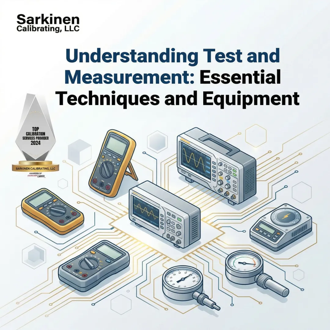
Common Tools and Techniques for Precision Measurement
Choosing the right measurement instrument depends on the tolerance you're working to, the part geometry, and your environment. The table below summarizes the six most common categories used in manufacturing.
Major Measurement Instrument Categories
| Instrument | Typical Accuracy | Governing Standard | Best Used For |
|---|---|---|---|
| Calipers (Vernier, Dial, Digital) | ±0.001–0.002 in (0.02–0.05 mm) | ASME B89.1.14-2018 | Quick dimensional verification of lengths, depths, and steps |
| Micrometers | ±0.0001 in (2.54 µm) | ASME B89.1.13-2013 | External/internal dimensions where caliper accuracy is insufficient |
| Dial Indicators | ±0.001 in to ±0.0001 in | ASME B89.1.10M-2001 | Setup verification and runout measurement against a reference |
| Gauge Blocks | ±0.14 µm (up to 25 mm) Grade 0 | ASME B89.1.9-2023 | Primary length calibration transfer standards |
| CMMs | MPE expressed as A + L/B µm (e.g., 0.9 + L/400 µm) | ISO 10360-2:2009 | 3D dimensional inspection with contact or scanning probes |
| Laser Systems (interferometers, trackers) | 15–50 µm over 30+ meters | ASME B89.4.19-2021 | Linear axis calibration and large-volume metrology |
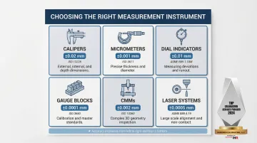
Each instrument category has a practical ceiling — when part tolerances tighten, you move up the list toward more precise (and more involved) measurement methods.
Contact vs. Non-Contact Measurement
Contact Measurement Methods involve the instrument physically touching the part. They're the right choice when:
- Surface finish can tolerate probe contact
- Part rigidity prevents deflection under probe force
- High accuracy is required for dimensional verification
- The measurement environment is controlled
ISO 230-10:2016 specifies test procedures to evaluate the measuring performance of contacting probing systems integrated with CNC machine tools, testing the combined influence of the machine tool, probe, and software.
Non-Contact Measurement Methods use laser, optical, or vision systems without touching the part. Advantages include:
- No risk of surface damage on delicate parts
- High-speed measurement suitable for production lines
- Ability to measure soft or flexible materials
- Measurement of surfaces that cannot be touched (hot parts, wet coatings)
ISO 10360-8:2013 specifies acceptance and reverification tests for CMMs equipped with optical distance sensors such as laser scanners and structured light systems.
Regardless of which approach you use, the instrument is only part of the equation. Environmental conditions matter just as much.
Measurement Best Practices
Temperature, vibration, and cleanliness can introduce errors even with high-quality instruments. Basic best practices include:
- Temperature Control: ISO 1:2022 legally fixes the standard reference temperature at exactly 20 °C (68 °F) for all dimensional properties. Measurements taken outside this environment require thermal compensation.
- Vibration Isolation: Mount precision instruments on isolated foundations or tables to minimize external vibration
- Cleanliness: Keep measurement surfaces and workpieces clean—a single chip or dirt particle can introduce significant error
- Proper Fixturing: Support parts adequately to prevent deflection under their own weight or measurement forces
The 10:1 Measurement Uncertainty Ratio
The 10:1 rule (Gagemaker's Rule) originated in the 1950 U.S. Military Standard MIL-STD-120, stating that the accuracy tolerances of measuring equipment should not exceed 10% of the tolerances being checked. In other words, a measuring instrument should be at least 10 times more precise than the tolerance being measured.
This rule ensures measurement uncertainty doesn't consume a significant portion of your tolerance band. In practice, though, increasingly tight manufacturing tolerances make 10:1 difficult to achieve with available instruments. Modern standards frequently accept a 4:1 Test Uncertainty Ratio (TUR) instead.
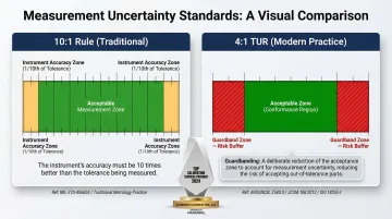
When a 10:1 ratio cannot be met, ASME B89.7.3.1-2001 and ISO 14253-1:2017 provide guidelines for "guardbanding"—mathematically reducing the acceptance zone by the magnitude of the measurement uncertainty to prevent false acceptance of non-conforming parts.
The Role of Calibration in Keeping Measurements Reliable
Even the most precise instruments drift over time due to wear, environmental exposure, and regular use. Periodic calibration against a traceable standard is essential, not optional.
Understanding NIST Traceability
NIST defines metrological traceability as the "property of a measurement result whereby the result can be related to a reference through a documented unbroken chain of calibrations, each contributing to the measurement uncertainty." This unbroken chain successively links a measurement result to the values and uncertainties of the highest reference standard—typically maintained by NIST or international equivalents.
Traceability is a property of the measurement result, not the instrument itself. When a calibration provider states their measurements are NIST-traceable, they're confirming that their calibration process can be documented back through a complete chain to national standards, with uncertainty quantified at each step.
That documentation gives manufacturers verifiable confidence in their measurement data. Without it, there's no way to prove your measurements are correct or comparable to those made by other facilities or regulatory bodies.
Calibration Intervals and Optimization
NIST explicitly states that it "does not require or recommend any set recalibration interval for measuring instruments, devices, or standards." Intervals depend on accuracy requirements, inherent stability, environmental factors, and usage patterns.
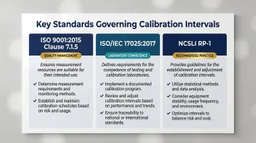
Three key standards govern how organizations approach calibration intervals:
- ISO 9001:2015 (Clause 7.1.5): Requires organizations to calibrate or verify measuring equipment at specified intervals against standards traceable to international or national references
- ISO/IEC 17025:2017: Mandates that testing and calibration laboratories maintain metrological traceability through a documented unbroken chain of calibrations
- NCSLI RP-1: Provides engineering and statistical methods—staircase methods, control charts, maximum likelihood estimation—for establishing and dynamically adjusting intervals based on historical reliability data
Local Calibration Advantages
Knowing the standards is one thing; having a calibration provider who can meet them consistently is another. For manufacturers in Portland OR and SW Washington, working with a local provider like Sarkinen Calibrating has practical benefits that go beyond compliance. Their measurements are traceable to NIST and international standards, achieving accuracy to 1.0 parts per million, which exceeds the minimum 10:1 ratio required for proper calibration results. Being local means faster response times when calibration is due or when an unexpected measurement issue arises, reducing equipment downtime and keeping production on schedule.
How Precision Measurement Errors Impact Manufacturing Operations
The consequences of measurement drift or tool error in a production environment compound quickly, affecting multiple aspects of operations.
The Financial Cost of Measurement Errors
Unplanned downtime costs large manufacturers an average of $260,000 per hour, according to Aberdeen research from 2022. In the automotive sector, the cost has risen to over $2 million per hour (Siemens, 2022). Across Fortune Global 500 firms, the average annual cost of unplanned downtime per facility reached $129 million in 2022—a 65% increase from 2020.
When measurement systems drift out of calibration, the downstream consequences include:
- Scrapping or reworking parts machined to incorrect dimensions
- Losing shipments to customer or third-party quality inspections
- Absorbing costly warranty returns from defective parts that reach the field
- Halting production for emergency troubleshooting and recalibration
Top-performing manufacturing facilities lose as little as 0.6% of their revenue to scrap and rework, while bottom-performing facilities lose up to 2.2%. Measurement system errors drive this Cost of Poor Quality (COPQ) by causing "false rejects" (scrapping perfectly good parts) and "false accepts" (releasing defective products to customers).

Turning Unpredictable Downtime into Predictable Maintenance
Proactive precision measurement practices—including regular verification of machine output and scheduled calibration—allow facilities to catch errors and damage before they become production stoppages. Instead of reacting to failures, manufacturers can schedule maintenance during planned downtime windows, minimizing disruption.
Calibration records and regular performance evaluations also serve as tangible proof to customers that machines deliver to spec—every time. For production facilities, that documentation supports better planning, reduces emergency repair costs, and gives quality teams the confidence to catch problems before they ship.
Frequently Asked Questions
What is precision measurement?
Precision measurement is the practice of quantifying physical properties—such as length, diameter, or position—to an extremely fine degree of exactness. It's used in manufacturing and engineering to verify that components meet tight specifications and to ensure repeatability across production runs.
How do you calculate precision?
Precision is calculated by taking a set of repeated measurements, finding the average deviation from their mean value, and expressing that deviation as a percentage of the mean. A smaller percentage means higher precision — measurements cluster more tightly together.
What is the difference between precise and precision?
"Precise" is the adjective describing a measurement or process that produces consistent, repeatable results, while "precision" is the noun referring to the quality or degree of that consistency. Neither term addresses whether a result is correct — only whether it's consistent.
What is an example of precision in manufacturing?
A CNC machine that cuts a part to 2.500 inches on five consecutive runs demonstrates high precision if all five measurements cluster tightly around 2.500 inches. This tight clustering indicates precision regardless of whether 2.500 inches is the target specification.
Why is precision measurement important in manufacturing?
Without reliable precision measurement, manufacturers cannot verify that parts meet specifications, catch equipment drift before it causes defects, or guarantee consistency across production runs. For CNC shops in particular, even small measurement gaps can translate directly into scrapped parts and missed delivery windows.