Introduction
CNC machine operators, machine shop managers, and production engineers constantly face a critical challenge: machining complex parts with features on multiple faces without accumulating positioning errors from repeated setups. Every time a workpiece is unclamped, repositioned, and re-indicated, uncertainty compounds—leading to tolerance stack-up, increased scrap rates, and longer cycle times.
A rotary axis addresses this challenge directly. It's a CNC axis that moves a workpiece or tool through angular (rotational) motion rather than linear travel, adding a new dimension of positioning to the machine.
Rotary axes appear constantly in multi-axis CNC discussions, yet the operational mechanics—how they interact with linear axes, how they're commanded, and what drives their accuracy—rarely get a clear shop-floor explanation. This article covers those fundamentals: axis types and designations, motion control, error sources, and what calibration actually verifies.
TL;DR
- A rotary axis enables machining on curved surfaces, multiple faces, or around a part's full circumference without re-fixturing
- Rotary axes are designated A, B, or C based on which linear axis they rotate around—not the same as 4th or 5th axis capability
- Rotary axes measure travel in degrees, not inches or millimeters, which changes how feedrates are programmed and how motion speed is calculated
- The most common configuration is the 4th axis (A-axis) for indexing or continuous rotation on 3-axis mills
- Accuracy degrades from backlash, gear reduction, wear, and thermal effects, making periodic calibration essential
What Is a Rotary Axis in CNC Machining?
A rotary axis is a programmable CNC axis that rotates a workpiece or cutting head around a fixed linear axis. Unlike linear axes, it moves through angular positions measured in degrees — not inches or millimeters. This lets the cutting tool reach multiple faces or the full circumference of a workpiece without the operator manually repositioning and re-indicating the part between operations.
How it differs from linear axes:
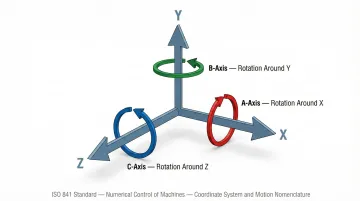
Linear axes (X, Y, Z) move in straight lines over measured distances in inches or millimeters. Rotary axes sweep through angular positions measured in degrees. The naming convention follows strict standards:
- A-axis rotates around the X-axis
- B-axis rotates around the Y-axis
- C-axis rotates around the Z-axis
This designation system, defined by ISO 841, ensures consistent programming and communication across different machine platforms and control systems.
How a Rotary Axis Works: From Setup to Cutting
A rotary axis works by receiving G-code commands with angular coordinates (in degrees), then driving the axis motor through a gear or worm drive to position the workpiece at the exact angle needed for the next cut. This happens in real time, synchronized with all active linear axes.
Core components include:
- Servo or stepper motor for rotational power
- Mechanical reduction system (worm gear, helical gear, or direct drive)
- Encoder or resolver for position feedback
- Controller that interprets angular coordinate values alongside linear axis commands
The key operational advantage is that rotational motion eliminates the need to manually re-clamp and re-indicate the part between operations. The workpiece holds a consistent datum throughout the machining cycle, which reduces accumulated positioning error.
Workpiece Mounting and Datum Setting
The workpiece is secured to a chuck, collet, or fixture mounted on the rotary axis faceplate. The operator or probing cycle establishes a rotational datum (home position) so the controller knows the angular reference point before any cutting begins. This initial setup is critical—without a reliable rotational zero, all subsequent angular positioning becomes meaningless.
Controller Interpretation and Axis Motion
The CNC controller reads angular coordinate values in the G-code (e.g., A90 = rotate 90 degrees) and drives the rotary axis motor accordingly. One point that catches many programmers off guard: the machine always moves at the rate of the slowest participating axis. Because rotary axes are programmed in degrees per minute while linear axes use inches or millimeters per minute, the actual surface speed at the cutting tool varies based on the tool's distance from the center of rotation.
The formula $v = \omega \times r$ governs this relationship (where $v$ is linear velocity, $\omega$ is angular velocity, and $r$ is radius). A feedrate that looks perfectly normal on paper can produce unexpectedly slow or fast rotary motion in practice. Without deliberate feedrate adjustments in CAM, the result is tool breakage or degraded surface finish.
Synchronized Cutting and Multi-Face Access
As the rotary axis positions the part, the linear axes continue cutting—enabling helical interpolation, circumferential milling, or sequential face machining in a single setup.
Two operational modes exist:
- Continuous mode: Simultaneous rotation and cutting for complex 3D surfacing
- Indexing mode: Rotate, lock, cut, repeat—used for multi-sided drilling and milling operations
Continuous mode requires advanced CAM programming and Tool Center Point Management (TCPM) to maintain consistent cutting conditions. Indexing mode is simpler to program and more common in production environments.
Types of Rotary Axes: 4th Axis vs. 5-Axis Configurations
The 4th Axis (A-Axis)
The most common entry point into multi-axis machining, the 4th axis is typically added to an existing 3-axis mill and rotates the workpiece around the X-axis. It's used primarily for indexing between faces or for cylindrical milling operations. Production-grade 4th axis rotary tables achieve angular positioning accuracies of ±2 to ±20 arc-seconds, with repeatability often within ±2 to ±6 arc-seconds.
5-Axis Configurations
A second rotary axis (B or C) is added alongside the A-axis, allowing the workpiece or spindle head to be positioned in true 3D space.
Two common layouts:
- Trunnion (table-table): Both rotary axes tilt and rotate the workpiece, delivering superior undercut access (+110°/-30° tilt) and strong rigidity for small-to-medium parts. Physical risers do limit the work envelope.
- Swivel-head (head-table): Rotary motion shifts to the spindle, keeping the table stationary and supporting massive parts (up to 30,000 kg on some models). The tradeoff is reduced rigidity compared to fixed-spindle setups.
Continuous 5-Axis vs. 3+2 Machining
How those five axes are used during a cut defines two distinct operating modes:
| 3+2 Machining | Continuous 5-Axis | |
|---|---|---|
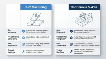
| Axis movement | Rotary axes lock before cutting; linear axes move | All five axes move simultaneously |
| Programming complexity | Simpler CAM setup, widely used in production | Advanced CAM, collision simulation, TCPM required |
| Best for | Prismatic parts, production runs | Complex sculptured surfaces, aerospace geometry |
Continuous Rotation vs. Indexing
Not every rotary device is a full axis — and the distinction matters when specifying equipment.
A true rotary axis moves to any angle continuously, guided by high-resolution encoder feedback. An indexer only stops at fixed, repeatable positions (for example, every 5° or 15°) using mechanical stops. Indexers cost less, but they cannot perform contouring operations. Confusing the two when purchasing or calibrating equipment leads to capability gaps that are expensive to correct later.
Where Rotary Axes Are Applied and Why
Industries and Part Types
Rotary axes are most commonly used in:
- Aerospace: turbine blades, structural brackets, and impellers requiring complex 3D surfacing
- Automotive: camshafts, impellers, and engine housings with multi-sided features
- Medical devices: orthopedic implants and surgical instruments with tight tolerances
- General job shops: complex prismatic or cylindrical parts requiring machining on multiple faces
Primary Operational Driver
Shops adopt rotary axes primarily to reduce the number of separate setups required to complete a part. Each time a workpiece is unclamped and re-indicated (re-zeroed to a reference datum), it introduces positioning uncertainty. A rotary axis keeps the part on a single datum from first cut to last.
The efficiency gains are well documented across real production environments:
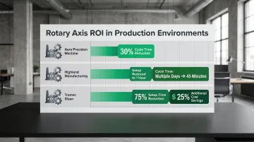
- Aero Precision Machine reduced cycle times by 30% using a direct-drive rotary system
- Highland Manufacturing cut setup time to one hour and cycle time from multiple days to 45 minutes
- Tramec Sloan reduced setup times by 75% and eliminated secondary operations, cutting costs by an additional 25%
Typical Triggers for Rotary Axis Use
Those ROI numbers don't happen by accident — they reflect situations where rotary axes are the right tool for the job. Common triggers include:
- Parts with features on more than two faces
- Cylindrical or helical geometry that cannot be produced on a flat table
- Production volumes where multiple setups per part make a rotary investment worth it
Key Factors That Affect Rotary Axis Accuracy and Performance
Angular Positioning Accuracy
Determined by the quality of the worm gear or drive mechanism, encoder resolution, and any backlash in the drivetrain.
Industry benchmarks:
| System Type | Typical Accuracy | Repeatability |
|---|---|---|
| Entry-level worm gear tables | ±12.5 arc-seconds | ±2 arc-seconds |
| Production-grade worm gear | ±10 to ±20 arc-seconds | ±4 to ±6 arc-seconds |
| High-precision with scales | ±3 to ±5 arc-seconds | N/A |
| Direct-drive systems | ±10 arc-seconds | Zero mechanical backlash |
Achieving sub-5 arc-second precision requires full closed-loop control using high-precision rotary encoders mounted directly to the table.
Feedrate and Speed Confusion
Rotary axes are programmed in degrees per minute, not inches or millimeters per minute. A seemingly normal linear feedrate can produce unexpectedly slow or fast rotary motion depending on the tool's distance from the center of rotation. Advanced control features like Heidenhain's TCPM or FANUC's G54.2 automatically convert deg/min to mm/min at the contour, preventing tool burn-out and poor surface finishes.
Mechanical Wear and Thermal Effects
Programming variables compound the physical degradation happening inside the machine itself. Worm gears and bearing surfaces wear continuously, and several failure modes develop slowly enough to go unnoticed until parts start failing inspection:
- Worm gear backlash typically doubles over a 5 to 10-year service life due to normal surface wear
- Heat from drive motors and cutting friction causes thermal expansion, shifting preload and angular positioning repeatability
- Accuracy drift from these sources is invisible without dedicated measurement
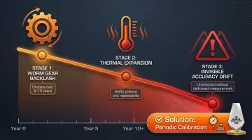
This is why calibration isn't just a commissioning task — it's an ongoing requirement.
Calibration and Verification
Unlike linear axes where ballbar or laser tests are routine, rotary axis calibration — measuring actual angular position against commanded position across the full 360-degree range — requires specialized equipment and NIST-traceable standards.
Specialized rotary axis calibrators, such as the Renishaw XR20-W paired with an XL-80 laser interferometer, provide non-contact calibration to ±1 arc second accuracy. At minimum, calibration should occur annually or after any crash or bearing service — but high-utilization facilities should treat it as condition-based. Sarkinen Calibrating serves Portland OR and SW Washington manufacturers with rotary axis calibration using Renishaw's Rotary Calibration System, verifying angular positioning accuracy, repeatability, and alignment before positioning drift turns into scrap.
Common Misconceptions and Limits of Rotary Axes
More Axes Don't Automatically Produce Better Parts
5-axis machines require significantly more complex CAM programming and setup validation. For simple prismatic parts or low-complexity cylindrical work, a 3-axis machine with a well-fixtured vise delivers equivalent quality — with less programming overhead and faster setup.
A Rotary Axis Is Not a Substitute for Proper Workholding
If the chuck or fixture doesn't grip the part rigidly, chatter, pull-out, or deflection will undermine the rotary axis's positioning capability entirely. The mechanical foundation has to be solid before the axis's angular precision can do any useful work.
Teams Often Misuse Rotary Axis Capability
Running a 5-axis machine in full continuous mode for parts that could be done effectively in 3+2 indexing wastes programming time and increases the risk of tool-path collisions. As a rule, use the minimum axis complexity that reliably achieves the required geometry. Common signs a shop is over-indexing on axis count:
- Cycle times are long but geometry is simple
- CAM programming takes longer than the actual job
- Tool-path collisions require repeated simulation passes
- Setup validation adds hours with no quality benefit
Conclusion
A rotary axis transforms a CNC machine by adding controlled angular positioning to the linear axes it already has, which lets parts with complex geometry, multiple faces, or cylindrical features be completed in fewer setups with consistent datum control.
That capability only delivers on its promise when the axis itself is performing accurately. Three factors determine whether it is:
- Accuracy limits — positioning error tolerances that define what the axis can reliably hold
- Feedrate behavior — how tangential velocity changes with distance from the centerline affect cut quality
- Calibration verification — periodic checks that confirm the axis still performs to spec under real production conditions
Without verified performance, multi-axis capability is an assumption, not a guarantee. Regular rotary axis calibration — the kind traceable to NIST standards — is what closes that gap.
Frequently Asked Questions
What is a rotary axis?
A rotary axis is a CNC axis that produces angular (rotational) movement rather than linear travel, typically designated A, B, or C based on which linear axis it rotates around. It's used to orient or continuously rotate a workpiece during machining without manual re-fixturing.
What is the difference between linear and rotary axis?
Linear axes (X, Y, Z) move in straight lines measured in inches or millimeters, while rotary axes sweep through angles measured in degrees. That difference carries over into programming — feedrates and positioning accuracy are specified in arc-seconds rather than linear units.
What does 5-axis mean in machining?
5-axis machining means the machine has three linear axes (X, Y, Z) plus two rotary axes (typically A and B or B and C), allowing the workpiece or spindle to be positioned in full 3D space for complex geometry without multiple re-fixturing operations.
What is the A-axis in CNC machining?
The A-axis is a rotary axis that rotates around the X-axis and is the most common 4th axis added to a 3-axis milling machine. It's typically implemented as a rotary table or trunnion to index or continuously rotate the workpiece during machining operations.
How often should a rotary axis be calibrated?
At minimum, angular accuracy checks should be performed annually — or immediately after any crash or bearing service. Usage intensity and tolerance requirements may call for more frequent checks, since undetected positioning drift can cause scrap before anyone notices the problem.
Can a rotary axis be added to an existing 3-axis CNC machine?
Yes, many 3-axis mills can accept a 4th axis rotary table as an accessory, provided the controller supports an additional axis input and the table size fits within the machine's work envelope and load capacity. For shops looking to expand into multi-axis work, adding a rotary table is typically the most practical first step.