
Introduction: Why Leveling and Alignment Are the Foundation of Precision Manufacturing
Unplanned downtime costs industrial manufacturers an average of $260,000 per hour, with equipment failures driving 42% of these incidents. Yet many of these failures trace back to one root cause: machines out of level or misaligned. Even minor deviations—measured in thousandths of an inch—cascade into scrap parts, rework, and emergency repairs that halt production lines.
This guide covers machine leveling and alignment specifically for industrial and CNC equipment. You'll learn core concepts, proven techniques, warning signs of geometric drift, and the professional calibration process. By the end, you'll know how to identify these problems early, prevent them through consistent measurement practices, and protect both part quality and equipment life.
TLDR:
- Geometric errors cause 45-65% of CNC part failures—more than programming or tooling issues combined
- Just 5 mils of misalignment can cut bearing life in half through accelerated wear
- Professional laser calibration reduces alignment time by 70% across 21 degrees of freedom
- Preventive calibration cuts downtime 30-50% and extends equipment life 20-40%
- NIST-traceable verification delivers documented proof for warranty claims and quality audits
What Is Machine Leveling and Alignment—and How Are They Different?
Machine leveling establishes a machine's reference plane relative to gravity. This creates a true, stable baseline from which all axes and structural components operate. Technicians measure leveling in arc-seconds or thousandths of an inch per foot—precision machinist levels typically resolve to 10 arc-seconds (0.0005 inches per foot), while advanced electronic levels measure down to 0.1 arc-seconds.
Machine alignment addresses the geometric relationship between moving and stationary components—spindles, linear guides, rotary axes, and mounting surfaces. Proper alignment ensures these components are parallel, perpendicular, or coaxial as the machine's design requires, verified through laser interferometry and dial indicator measurements.
Why Both Must Be Addressed Together
Leveling establishes the foundation; alignment ensures components operating on that foundation relate correctly to each other. Skip one, and you undermine the other. The consequences are concrete:
- A perfectly aligned spindle on an unlevel bed will still produce tapered parts
- A level machine with misaligned axes will wear guides unevenly and produce dimensional errors that no software compensation can permanently fix
Why Leveling and Alignment Directly Impact Production Quality and Efficiency
Dimensional Accuracy Suffers First
A machine operating out of level introduces systematic errors into every part it produces—errors that are repeatable but invisible until measured against specification. Research shows that geometric and thermal errors account for 45% to 65% of all CNC machine tool error sources, directly causing tapered bores, out-of-round parts, and poor surface finishes. Geometric errors alone drive 30% of machine inaccuracies, outpacing both programming and tooling errors combined.
Component Wear Accelerates Exponentially
Misalignment creates uneven load distribution on linear guides, ball screws, and bearings. Engineering studies demonstrate that just 5 mils (0.005 inches) of offset misalignment can reduce rolling element bearing life by up to 50% due to edge loading and localized stress. This premature wear increases vibration, introduces backlash, and leads to mechanical failure if left uncorrected.

Unplanned Downtime Multiplies Costs
Beyond the immediate repair cost, machine failures carry a "restart tax" of 30 to 120 minutes of lost production per incident. That window includes thermal stabilization (15–45 minutes), process re-qualification for regulated industries, and scrapped material from the first post-restart batch. Misalignment and leveling drift rank among the leading causes of these failures.
New Machine Warranty Protection
Regular verification catches alignment problems before they escalate into emergency repairs — but that discipline matters most when a machine is brand new. Verifying geometry before production begins is the only way to confirm a machine meets its promised specifications while still under warranty. Shipping and installation frequently introduce alignment errors or hidden damage. Catching these issues early prevents them from becoming your cost six months into production.
Key Techniques and Tools for Precision Leveling and Alignment
Precision Leveling Methods
Precision levels — both electronic and spirit — form the foundation of leveling work. The reference-point method establishes a "home" position on the machine bed, then references all other measurement points to it. Technicians measure side-to-side and front-to-back to achieve true planar leveling across the entire structure.
Electronic levels like the Mahr Federal 832 deliver resolutions down to 0.1 arc-seconds (6 microinches per foot), far exceeding the 10 arc-second capability of traditional spirit levels. Even minor angular deviations affect accuracy on long-travel machines or large CNC routers — which is why instrument selection matters.
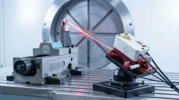
Laser Alignment Systems
Laser alignment tools project a highly accurate reference beam to check:
- Parallelism between axes
- Straightness of linear guides
- Squareness of perpendicular axes
- Flatness of mounting surfaces
Laser interferometers reduce alignment time by up to 70% compared to mechanical methods while capturing data across multiple degrees of freedom simultaneously. For machines longer than 10 feet or multi-axis CNC routers, laser-based measurement is the preferred approach due to cumulative error in traditional straight edges and dial indicators.
Spindle and Axis Alignment Techniques
Technicians verify spindle alignment using:
- Test bars mounted in the spindle taper
- Dial indicators to measure runout and perpendicularity
- Sweep methods that rotate the spindle through a full circle while measuring deviation
Linear axis verification checks that axes are square and parallel to one another within specified tolerances, typically measured in arc-seconds for angular error and microinches for straightness deviation.
The 4:1 Test Uncertainty Ratio Principle
Modern ISO/IEC 17025 and ASME B89.7.3.1 standards rely on a 4:1 Test Uncertainty Ratio (TUR) for simple acceptance decisions. This means measuring instruments must be at least four times more accurate than the tolerance being checked. Professional calibration services operating with NIST-traceable instruments achieve measurements well beyond this ratio — Sarkinen Calibrating's laser interferometer delivers accuracy to 1.0 parts per million, providing reliable results even for tight aerospace and medical device tolerances.
Environmental and Installation Factors
Measurement technique is only part of the equation. Floor flatness, vibration sources, thermal expansion, and machine anchoring all affect leveling and alignment outcomes. Technicians must account for:
- Foundation settling or concrete cracking
- Nearby press operations causing vibration
- HVAC airflow creating thermal gradients
- Inadequate anchor bolt torque or shimming
Technicians must assess these variables before and during precision work to protect measurement integrity — otherwise even the most accurate instruments can't compensate for an unstable foundation.
Warning Signs Your Machine Needs Leveling or Alignment Correction
Production-Side Symptoms
Watch for these measurable signs:
- Out-of-tolerance dimensions on finished parts, especially when the same error appears consistently
- Inconsistent surface finishes across the workpiece
- Progressive dimensional drift across a production run—parts 1-10 are in spec, parts 50-60 are borderline, parts 100+ are scrap
- Increased compensation parameters in the CNC control to maintain tolerance
Mechanical Warning Signs
The machine itself reveals geometric problems:
- Unusual vibration during rapids or cutting
- Increased cutting noise or chatter that wasn't present previously
- Uneven wear on linear guides or ball screws
- Recurring axis positioning errors that cannot be corrected through software compensation alone
- Steadily increasing backlash requiring larger compensation values
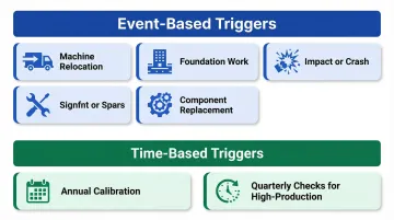
Time-Based and Event-Based Triggers
Check leveling and alignment after:
- Machine relocation (even a 10-foot move requires re-leveling)
- Foundation work or floor repairs near the machine
- Significant impact—a forklift strike, dropped tooling, or crash
- Component replacement—new ballscrews, linear guides, or spindle installation
- Regular intervals: annual calibration is the standard baseline, with quarterly checks for high-production environments
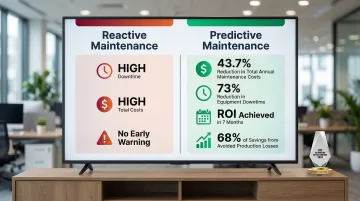
Predictive maintenance reduces downtime by 30-50% and extends equipment life by 20-40% compared to reactive, run-to-failure approaches — reason enough to schedule checks before symptoms appear.
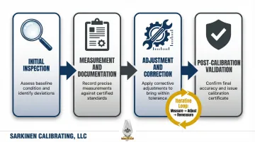
The Professional Calibration Process: From Baseline Inspection to Verified Performance
Initial Inspection Phase
A professional calibration visit begins with comprehensive assessment of the machine's current geometric state. Technicians evaluate:
- Existing level across multiple measurement points
- Axis straightness using electronic levels or laser systems
- Squareness between perpendicular axes
- Visible signs of mechanical wear or damage affecting measurement validity
This inspection identifies not just current geometry but also root causes—foundation settlement, inadequate shimming, or component wear requiring correction before calibration proceeds.
Measurement and Documentation Phase
All baseline readings are recorded before adjustments begin. This traceable record serves three critical functions:
- Documenting geometry errors that existed upon delivery for warranty claims
- Proving compliance with ISO 230-1 or ASME B5.54 standards during quality audits
- Tracking geometric drift over time to predict future maintenance needs
ISO/IEC 17025:2017 compliant reports must include unique identification, measurement method, results with units, measurement uncertainty, environmental conditions, and metrological traceability statement.
Adjustment and Correction Phase
With baseline data in hand, technicians make targeted adjustments across three areas:
- Shimming the bed to correct twist or sag
- Repositioning components to restore perpendicularity between axes
- Re-tensioning gibs and ways to eliminate excess clearance
The process is iterative: measure, adjust, re-measure, until all parameters fall within specification. A typical multi-axis machining center requires 4–6 hours for complete geometry correction.
NIST-Traceable Verification
NIST defines metrological traceability as the "property of a measurement result whereby the result can be related to a reference through a documented unbroken chain of calibrations, each contributing to the measurement uncertainty." For manufacturers, that chain of documentation is often required by quality management systems and by customers auditing supplier capability.
Sarkinen Calibrating's measurements are traceable to NIST and International Standards, providing the documented proof manufacturers need when bidding contracts or responding to regulatory audits.
Post-Calibration Validation
Final verification re-measures all parameters after adjustment to confirm the machine holds specification. A thorough calibration report accompanies every service visit, including:
- Before and after measurements for each axis
- Graphical representation of error (Moody plots for flatness, circularity plots for ballbar tests)
- Pass/fail determination against specification
- Recommendations for future maintenance
When to Call a Professional Calibration Service
Scenarios Requiring Outside Expertise
In-house checks using basic levels and indicators are useful for routine monitoring. However, these scenarios warrant certified, NIST-traceable professional calibration:
- New machine commissioning — Shipping and installation often introduce geometry errors that fall on you if not caught while the machine is still under warranty
- Post-relocation verification — Moving a machine invalidates previous calibration; professional verification confirms the new installation meets spec before production resumes
- Warranty disputes — Documented, traceable measurements provide objective evidence when challenging a manufacturer's claim that a machine meets spec
- Quality audit preparation — ISO 9001, AS9100, and ISO 13485 auditors expect calibration records traceable to national standards, not informal in-house checks
- Chronic part-quality problems — When programming, tooling, and workholding have been ruled out, professional geometric verification often reveals the root cause
The Case for Scheduled Preventive Calibration
Waiting for visible problems before calibrating is the most expensive approach. By the time symptoms appear in production—scrap parts, dimensional drift, excessive wear—damage and quality losses have already accumulated.
A case study on predictive maintenance in CNC machining found total annual maintenance costs dropped 43.7% and equipment downtime fell 73%, with diagnostic equipment paying for itself in just 7 months. The primary savings (68%) came directly from avoided production losses.
A scheduled calibration program eliminates that accumulated-damage risk and supports consistent machine output. For high-production environments, quarterly precision checks and annual complete geometry verification align with OEM recommendations from manufacturers like DMG Mori and Okuma.
Local Service Advantage
For manufacturing facilities and machine shops in Portland OR and SW Washington, working with Sarkinen Calibrating means faster response times and less disruption to production schedules than relying on out-of-area services. When a machine goes down or a new installation needs verification before production begins, local availability means less waiting and fewer lost production hours.
Frequently Asked Questions
What is the difference between leveling and alignment on a CNC machine?
Leveling sets the machine's reference plane relative to gravity, establishing a stable baseline for all components. Alignment verifies the geometric relationship between machine components—ensuring axes are parallel, perpendicular, or coaxial as designed. Both are required for accurate, consistent output.
How often should machine leveling and alignment be checked?
Frequency depends on machine type, usage intensity, and environment. Annual calibration is a standard baseline, with additional checks after relocations, impacts, or major component replacements. High-production environments benefit from quarterly verification to catch geometric drift before it affects part quality.
What are the most common signs that a machine is out of level or misaligned?
Common signs include out-of-tolerance part dimensions, surface finish inconsistencies, progressive dimensional drift across production runs, unusual vibration, and accelerated wear on guides or screws. If you're increasing backlash compensation parameters in the CNC control, that's another signal of geometric degradation.
Can machine leveling and alignment be done in-house, or does it require a professional?
Routine monitoring can be done in-house with basic levels and indicators. However, precision verification to NIST-traceable standards—required for warranty documentation, quality audits, and initial commissioning—requires calibrated instruments and trained technicians who can achieve the 4:1 test uncertainty ratio standard. Services like those provided by Sarkinen Calibrating deliver that traceability for facilities in the Portland OR and SW Washington area.
What tolerances are typically required for precision machine leveling?
Most precision machines require leveling within 0.0005 inches per foot (approximately 3 arc-seconds). High-accuracy CNC and grinding equipment demand tighter tolerances—often 0.1 arc-seconds or better—which requires electronic levels or laser measurement systems to achieve reliably.