Introduction
Picture this: A machine shop runs a final inspection on a batch of precision-machined flanges. Every dimension checks out—holes are on center, parallelism is within spec, surface finish is smooth. But when the parts reach assembly, they won't seal. Hours of rework follow, and the root cause? The reference surface used to fixture the part during inspection wasn't flat.
Flatness measurement is a critical but often skipped step in precision manufacturing. When datum surfaces deviate from true flatness, every measurement taken from that reference carries projected error—leading to false part rejections, assembly failures, and costly production delays.
This guide covers:
- What flatness means in GD&T terms
- Which tools measure it accurately
- How to apply a reliable measurement process
- The most common mistakes that undermine flatness inspection
TL;DR
- Flatness measures how closely all surface points lie within two parallel planes; that gap between the planes is the flatness value
- Non-flat datum surfaces project errors across every feature measured from them, causing false rejections and expensive rework
- Tools range from feeler gauges to CMMs and laser scanners, each trading off accuracy, part size, and operator skill
- Reliable results depend on matching the tool to the tolerance, scanning systematically, and interpreting outputs against the tolerance zone
- Measurement instruments themselves must be calibrated regularly; uncalibrated tools invalidate every flatness result they produce
What Is Flatness in Manufacturing?
Flatness is a GD&T form control that defines a surface condition where all points must lie between two parallel imaginary planes. The distance between those planes is the flatness value. For example, a 0.1 mm flatness callout means every surface point must fall within a 0.1 mm tolerance zone bounded by two parallel planes.
The Tolerance Zone Concept:
Picture two parallel planes pressed as close together as possible while still enclosing every measured surface point — the gap between them is the flatness value. The narrower that gap, the flatter the surface. This minimum-zone method is the recognized evaluation criterion required by international standards like ASME Y14.5 and ISO 1101.
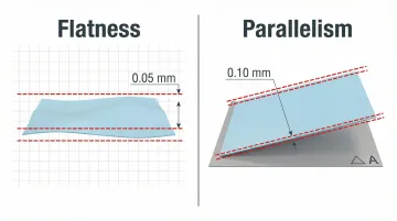
Flatness vs. Parallelism:
These two controls are often confused, but they measure different things:
- Flatness is self-referencing — no datum required. It defines how flat a surface is relative to itself.
- Parallelism compares a surface to a separate datum plane. A surface can pass a flatness check and still fail a parallelism check.
A tabletop can be perfectly flat yet tilted at an angle to the floor — flatness confirmed, parallelism violated.
Why Flatness Measurement Matters in Manufacturing
Datum Alignment and Measurement Error Propagation
A datum surface with even a 0.05 mm flatness error carries that error through to every feature measured from it — holes, slots, mating faces, all of it. The coordinate system itself becomes skewed.
That means engineers can incorrectly reject well-machined parts or miss real defects, not because the machining was wrong, but because the reference plane wasn't flat to begin with.
Assembly and Sealing Impact
Surfaces that mate together—gaskets, flanges, mounting faces—depend on flatness to form tight seals and repeatable contact. Poor flatness leads to:
- Fluid leaks in hydraulic and pneumatic systems
- Vibration and noise from inconsistent clamping
- Uneven load distribution causing premature wear
- Inconsistent torque values during bolt-up
Standards like ASME B16.5 specify flatness tolerances for flange faces to ensure joint integrity. Hard gaskets may only seal radial flatness deviations of less than 0.006 inches, while soft gaskets can accommodate up to 0.01 inches.
The Calibration Connection
Measuring instruments used for flatness checks—surface plates, height gauges, CMMs—require regular calibration against NIST-traceable standards. An uncalibrated reference surface or tool introduces systemic error that corrupts every measurement taken with it. Worn surface plates develop localized "dishing" that invalidates flatness readings, causing parts to be incorrectly approved or rejected.
That's the risk a drifted surface plate creates — not just one bad reading, but a pattern of bad decisions built on a compromised reference. Sarkinen Calibrating provides NIST-traceable calibration for surface plates and measurement equipment across Portland OR and SW Washington, so the tools you rely on for flatness inspection are actually giving you numbers you can trust.
Flatness Measurement Tools Explained
The right tool depends on your surface size, tolerance requirements, part accessibility, and available setup time. Each method below has a different sweet spot — here's how they compare:
Feeler Gauge and Surface Plate Method
Place the part on a precision granite surface plate, which rests on three contact points. Slide feeler gauge strips of known thickness under the part to find the gap. The thickest strip that fits is your flatness deviation.
This method is straightforward, but its accuracy depends entirely on the operator covering all areas systematically. Other practical limits:
- Large surfaces (for example, 4 ft × 8 ft panels) cannot be fully reached
- The center of a large part may be unmeasurable with a standard feeler gauge
- Complex geometries prevent complete coverage
Height Gauge with Dial Indicator
The part rests on a surface plate while a height gauge with a dial indicator or ruby probe sweeps across the surface, recording maximum and minimum height readings. The range between them is the flatness value.
How the part is supported changes what you're actually measuring — and this distinction matters:
- Direct placement: Resting the part flat on the table measures parallelism to the table, not true flatness. This produces false negatives for parts that should fail.
- 3-column method: Three adjustable columns let the operator minimize the amplitude range to find the true "smallest sandwich," isolating datum-independent flatness.
The 3-column method is essential for measuring true flatness rather than parallelism to the reference surface.
CMM (Coordinate Measuring Machine)
A CMM uses a touch probe to collect discrete data points across a surface. Software then calculates flatness from the point cloud using a minimum-zone fit (Chebyshev method).
Like manual methods, a CMM can miss the true peak or valley if the probe path is sparse. Studies show sparse CMM sampling can underestimate true flatness errors by an average of 10% due to missed local features. A dense, systematic scan path is critical.
3D Laser Scanning and Advanced Sensors
3D laser scanners capture a high-density point cloud across the entire surface in a single pass — often millions of points with spacing as tight as 0.03 mm. This dramatically reduces the chance of missing peak or valley points compared to touch-probe methods.
One rule governs sensor selection: resolution should be at least 10× finer than the tolerance being measured. To verify a ±3 µm flatness tolerance, the sensor must resolve down to ~300 nm. Surface properties also matter — reflective, transparent, or textured surfaces each require a different sensor type.
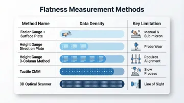
Flatness Measurement Tool Comparison:
| Tool / Method | Data Density | Key Limitation |
|---|---|---|
| Feeler Gauge + Surface Plate | Manual spot checks | Operator-dependent; large surfaces unreachable |
| Height Gauge (Direct on Plate) | Continuous line | Measures parallelism, not true flatness |
| Height Gauge (3-Column Method) | Continuous line | Requires operator skill to level correctly |
| Tactile CMM | Sparse point cloud | Low point density can miss local peaks/valleys |
| 3D Optical Scanner | Millions of points | Requires line-of-sight; surface finish sensitive |
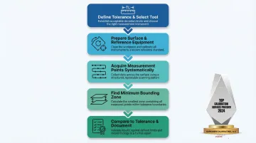
How to Measure Flatness: A Step-by-Step Process
This process applies across tool types and reflects shop-floor best practices.
Step 1 – Define the Tolerance and Select the Right Tool
- Identify the flatness tolerance from the engineering drawing or GD&T callout
- Apply the 10:1 ratio rule: measurement resolution must be at least 10× finer than the tolerance
- Choose the appropriate tool based on surface size, accessibility, and tolerance level
For a 0.05 mm flatness tolerance, for example, your measurement tool must resolve to at least 0.005 mm (5 µm).
Step 2 – Prepare the Surface and Reference Equipment
Once you've matched the tool to the tolerance, the next variable is the environment itself. Physical setup errors corrupt results before measurement even begins:
- Clean the surface and reference equipment (surface plate, CMM table) to remove chips, coolant, and debris — particulate contamination is a leading cause of false high readings
- Verify the surface plate or CMM reference datum is itself within calibration
- Allow thermal soak-out time so parts and instruments reach thermal equilibrium with the metrology environment
Thermal gradients and contamination introduce systematic measurement errors that corrupt flatness results.
Step 3 – Acquire Measurement Points Systematically
Scan coverage determines whether your result reflects reality. Sampling only the perimeter or easy-access areas risks missing the true high and low points entirely.
- Scan the entire surface using a grid or cross-pattern path for manual methods
- For CMMs and scanners, define point density relative to surface size and tolerance
- Denser sampling catches deviation patterns that sparse grids mask
Step 4 – Find the Minimum Bounding Zone (Smallest Sandwich)
Fit two parallel planes to the point cloud so all points fall between them. The distance between those planes — minimized as tightly as possible — is the flatness value.
- CMM/scanner software does this automatically using a minimum-zone (Chebyshev) algorithm
- Manual methods require careful adjustment of the 3-column setup to minimize indicator range
Step 5 – Compare to Tolerance and Document
- Compare the measured flatness value against the drawing callout
- If using datum surfaces, confirm flatness before using them as alignment references
- Document results and flag any surfaces that are out of tolerance before proceeding to further machining or assembly
Common Flatness Measurement Mistakes and How to Avoid Them
Skipping Flatness Checks on Datum Surfaces
Using a non-flat datum surface corrupts every downstream measurement on the part — making it one of the costliest errors in a flatness inspection. If the reference surface isn't flat, nothing measured against it can be trusted. Always verify datum flatness before running a full inspection.
Measuring with an Uncalibrated Surface Plate or Instrument
A surface plate that has worn or been damaged introduces systematic bias into every measurement. Regular, NIST-traceable calibration of both reference surfaces and instruments is non-negotiable — the widely accepted 10:1 calibration ratio standard exists precisely to prevent measurement uncertainty from compounding across the inspection process.
Best practice: Schedule periodic local flatness checks using a repeat-reading gage to detect localized wear before it causes false rejections.
Confusing Flatness with Parallelism
Placing a part directly on a surface plate and scanning it with a height gauge measures parallelism to the table, not true flatness. Parts that fail this test may actually be within flatness tolerance. The 3-column adjustment method — which mathematically removes the reference plane tilt from the data — is the correct approach for isolating true flatness from parallelism error.
Using Least-Squares Instead of Minimum-Zone Evaluation
Many CMMs default to a Gaussian (Least Squares) fit, which averages data points but is not the correct method for GD&T flatness evaluation. The Chebyshev (Minimum Zone) evaluation must be explicitly selected to correctly evaluate flatness. Check your CMM software settings before running the inspection to confirm the correct algorithm is active.
How Sarkinen Calibrating Supports Precision Measurement
Flatness measurement is only as accurate as the tools doing the measuring. Surface plates, height gauges, CMMs, and other reference instruments must be regularly calibrated to maintain the accuracy required for valid flatness results.
Sarkinen Calibrating provides NIST-traceable calibration for measurement equipment used in precision manufacturing operations across Portland OR and SW Washington. Founded by Larry, a former machine operator, the company approaches calibration from a production floor perspective, focused on how calibration errors translate into real production problems, such as false part rejections and unnecessary rework.
Key advantages:
- Exceeds the 10:1 accuracy ratio required for proper calibration, with accuracy to 1.0 parts per million
- Faster local response times reduce unplanned downtime compared to out-of-area providers
- Performs on-site surface plate leveling and flatness verification using Moody Plot analysis, eliminating shipping delays
When reference equipment is calibrated to this standard, flatness data holds up under scrutiny — whether you're resolving a warranty dispute, defending a quality audit, or tracing the source of a recurring production defect.
Frequently Asked Questions
How is surface flatness measured?
Flatness is measured by collecting points across a surface using feeler gauges, height gauges, CMMs, or 3D scanners, then finding the minimum distance between two parallel planes that enclose all points. That distance is the flatness value.
What does 0.1 flatness mean?
A 0.1 flatness callout means all points on the surface must lie within a tolerance zone of 0.1 mm (or 0.1 of whatever unit is specified), defined by two parallel planes exactly 0.1 apart. A point outside that zone means the surface fails the callout — even if it looks flat to the eye.
What is the difference between flatness and parallelism?
Flatness is a self-contained form control (no datum required) measuring how flat a surface is relative to itself. Parallelism compares a surface to a separate datum—a surface can be flat but still not parallel to another surface.
What tools are used to measure flatness?
Main tools include feeler gauges with a surface plate, height gauges with dial indicators, coordinate measuring machines (CMMs), and 3D laser scanners. Tool choice depends on surface size, required accuracy, and part accessibility.
Why does flatness measurement matter in CNC machining?
In CNC environments, datum surfaces that are not flat cause all downstream measurements to carry projected errors. This leads to false part rejections, wasted rework cycles, and tooling adjustments that address the wrong problem.
How often should flatness measurement tools be calibrated?
Calibration frequency depends on usage intensity and tolerance requirements. Instruments in precision manufacturing environments should follow a schedule traceable to NIST or international standards. High-use or tight-tolerance applications typically warrant more frequent checks to catch drift before it affects part quality.