This guide covers the meaning of surface finish, how it's measured, key parameters like Ra and RMS, how to read specifications on drawings, and why measurement tool accuracy matters on the shop floor. Whether you're programming CNC operations or verifying parts in inspection, understanding surface finish measurement ensures your parts meet specifications the first time—and stay within tolerance throughout production runs.
TLDR:
- Surface finish encompasses roughness, waviness, and form—three distinct characteristics that must be separated through filtering during measurement
- Ra (arithmetic average roughness) is the international standard; RMS (Rq) is more sensitive to peaks but has no reliable conversion formula
- Contact stylus profilometers are the most common measurement method, requiring regular calibration against NIST-traceable reference standards
- A 3.2 µm Ra specification means moderately smooth finish—achievable with standard turning or milling
- Uncalibrated instruments produce unreliable results that can pass defective parts or reject good ones
What Is Surface Finish? (Roughness, Waviness, and Form)
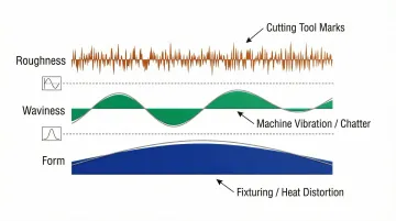
Surface finish refers to the complete texture of a machined surface, encompassing three distinct characteristics: roughness, waviness, and form. Each characteristic reveals different information about the machining process and the part's functional performance — so measuring only roughness gives you an incomplete picture.
All three characteristics appear together on any real machined surface. Measurement instruments separate them through filtering — without it, a roughness reading can absorb waviness from machine chatter, producing an Ra value that misrepresents the actual texture.
Here's how each characteristic is defined and where it comes from:
Roughness
Roughness refers to the fine, closely spaced irregularities inherent to the manufacturing process itself—the marks left directly by the cutting tool, abrasive grit, or machining method. It's the most commonly measured aspect of surface texture because it governs friction, wear, sealing, and fatigue life.
Typical roughness features include:
- Feed marks from turning or milling operations
- Grinding wheel grit patterns
- Tool nose radius impressions
- Built-up edge artifacts from cutting
Roughness is measured in micrometers (µm) or microinches (µin) and typically ranges from 0.025 µm for polished surfaces to 12.5 µm for rough machining.
Waviness
Waviness refers to broader, more widely spaced undulations superimposed on roughness, typically caused by machine vibration, chatter, or workpiece deflection. Separating waviness from roughness requires filtering during measurement, using a long-wavelength cutoff (λc) that removes these larger-scale features from the roughness profile.
Common causes of waviness include:
- Machine tool vibration or resonance
- Chatter from unstable cutting conditions
- Workpiece deflection during machining
- Heat-induced distortion
- Worn machine slideways or bearings
Measuring waviness separately from roughness requires a skidless (datum) profilometer for accurate results.
Form
Form represents the overall macro-shape of the surface—flatness, straightness, or curvature—ignoring both roughness and waviness. Form errors typically stem from fixturing problems, slideway inaccuracy, or heat-induced distortion during machining.
Examples of form errors include:
- Bowed or warped surfaces from thermal expansion
- Taper from misaligned machine axes
- Concavity or convexity from spindle deflection
- Straightness errors from worn guideways
Engineers typically evaluate form using separate geometric measurement methods — coordinate measuring machines, laser trackers, or straightedges — rather than surface finish instruments.
Key Surface Finish Parameters Explained
Surface texture parameters are the numerical values that quantify surface characteristics. They fall into three categories: amplitude parameters (vertical), spacing parameters (horizontal), and hybrid parameters. Most manufacturing specifications focus on amplitude parameters, which measure the height variations of the surface profile.
Ra – Roughness Average
Ra is the arithmetic mean of the absolute deviations of the surface profile from the mean line, measured over the evaluation length. It's the most universally used and internationally recognized roughness parameter, expressed in micrometers (µm) or microinches (µin).
How Ra is calculated: The profilometer traces the surface profile, establishes a mean line through the profile data, measures the absolute distance of each point from that mean line, and averages those distances across the evaluation length.
Why Ra dominates specifications:
- Simple to understand and communicate
- Stable and repeatable across different instruments
- Internationally standardized (ISO 4287, ASME B46.1)
- Effective for general process control
- Suitable for most stochastic (random) and periodic surface textures
Ra values typically range from 0.025 µm for mirror-polished surfaces to 25 µm for rough-sawn or as-cast surfaces.
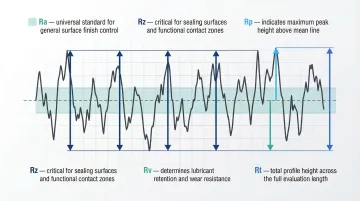
Rz, Rp, Rv, and Rt
Four secondary parameters provide additional insight when Ra alone doesn't capture critical surface characteristics:
- Rz (average peak-to-valley height): The sum of the highest peak and deepest valley within a sampling length, averaged over five sampling lengths per ISO 4287. Critical for sealing surfaces where protruding peaks cause leakage.
- Rp (maximum peak height): Height of the highest peak above the mean line within the sampling length. Important for surfaces prone to rapid initial wear during run-in.
- Rv (maximum valley depth): Depth of the deepest valley below the mean line within the sampling length. Essential for assessing lubricant retention capabilities in cylinder bores or bearing surfaces.
- Rt (total height of profile): Vertical distance between the absolute highest peak and deepest valley over the entire evaluation length. Used in strict tolerance environments where a single deep scratch causes rejection.
These parameters are more sensitive to extreme features than Ra. A surface might have acceptable Ra but fail on Rz due to isolated deep scratches or protruding burrs.
Ra vs. RMS (Rq)
RMS (also called Rq) is calculated as the square root of the mean of the squared deviations from the mean line, making it more sensitive to large isolated peaks or flaws than Ra. RMS was the dominant US standard historically and still appears on older drawings; Ra is the current international standard for most applications.
There is no reliable direct conversion between Ra and RMS. The commonly used multipliers each apply to a specific surface model:
- 1.11x multiplier (Rq ≈ 1.11 × Ra): Mathematically accurate only for perfectly sinusoidal surfaces
- 1.25x multiplier (Rq ≈ 1.25 × Ra): Applies to surfaces with Gaussian (random) height distribution
- Real machined surfaces: Periodic tool marks, skewed valleys, or isolated peaks cause both models to break down
If a drawing specifies RMS, measure and report RMS using an instrument calibrated for that parameter — don't convert from Ra using a formula. If you must estimate, Rq is typically 10–25% higher than Ra for most machined surfaces, but confirm with the customer or engineer rather than relying on a conversion factor that may introduce real measurement error.
How Surface Finish Is Measured: Methods and Tools
Surface finish measurement uses three broad approaches—contact (tactile/stylus-based), non-contact (optical), and comparative methods. Each approach is appropriate based on part geometry, material, and required precision.
Contact Measurement: Stylus Profilometers
A stylus profilometer works by dragging a fine diamond-tipped stylus across the surface at constant speed. The vertical displacement of the stylus generates an electrical signal; the instrument amplifies and processes this signal to calculate roughness parameters.
Standard stylus specifications (ISO 3274):
- Tip radius: 2 µm for general use (5 µm or 10 µm for rougher surfaces)
- Cone angle: 60° or 90°
- Material: Diamond (for wear resistance)
- Measuring force: 0.75 mN to 4 mN
A worn or oversized stylus tip acts as a mechanical low-pass filter, failing to penetrate fine valleys and artificially lowering Ra readings on fine finishes. Implement strict stylus inspection and replacement schedules to prevent passing out-of-spec parts.
Skidded profilometers:
- Use a mechanical skid resting on the workpiece as the reference datum
- Simpler and suitable for shop floor use
- Ideal for quick production checks of Ra on flat or cylindrical parts
- Limitation: The skid physically filters out waviness and form, so they cannot measure step heights or true Rz accurately
Skidless (datum) profilometers:
- Measure relative to an internal precision-lapped reference bar
- Required when waviness or form also need to be captured
- Suitable for laboratory environments and complex measurements
- More sensitive to environmental vibration and require careful leveling
Non-Contact and Comparative Methods
Optical/non-contact methods offer advantages for soft, delicate, or very smooth surfaces where stylus contact could damage the part:
- Coherence Scanning Interferometry (CSI): Uses white-light interferometry to achieve sub-nanometer vertical resolution. Ideal for ultra-smooth, reflective surfaces (optics, semiconductor wafers), but struggles with steep slopes.
- Focus Variation Microscopy: Analyzes changes in focus as optics scan vertically to capture topography. Excels on rougher, diffuse surfaces and can measure steep flanks up to 87°.
- Laser Triangulation: Calculates distance based on reflected laser spot position. Offers large measuring ranges but is sensitive to surface reflectivity and scattering.
Comparative/visual methods (surface roughness comparison plates, fingernail drag test) provide quick shop floor checks but are subjective and not suitable as a substitute for instrument measurement when a specification must be verified.
Instrument Calibration and Measurement Accuracy
Selecting the right measurement method only matters if the instrument producing those readings is verified against known standards. Calibration relies on physical artifacts categorized by ISO 5436-1:
- Type A (depth standards): Wide grooves used to calibrate vertical (Z-axis) amplification
- Type B (tip condition): Narrow grooves sensitive to stylus geometry, verifying the 2 µm diamond tip hasn't chipped or worn flat
- Type C (spacing standards): Grids of repetitive grooves used to check horizontal transmission and Ra accuracy
- Type D (roughness standards): Unidirectional irregular profiles (ground surfaces) for overall system verification
Surface finish measurements are only as reliable as the machines producing the parts being inspected. For manufacturers in Portland, OR and SW Washington, Sarkinen Calibrating provides NIST-traceable calibration for the CNC machine tools at the start of that chain — verifying linear axes, rotary axes, and surface plate flatness so that dimensional accuracy is confirmed before a part ever reaches inspection. Founder Larry started as a machine operator, which means his approach to calibration is grounded in how accuracy problems on the machine floor translate into rejected parts and production delays.
How to Read Surface Finish Specifications on Engineering Drawings
The GD&T surface finish symbol (the check-mark-style symbol with a horizontal line) appears on engineering drawings to specify surface texture requirements. Understanding the key elements—the Ra/Rz value (in µin or µm), the lay symbol, and any additional notes—ensures you interpret what the drawing is actually requiring.
Symbol elements:
- Material removal indicator: A horizontal bar across the top indicates machining is required; a circle inside the vee indicates material removal is prohibited (as-cast or forged)
- Parameter placement: The roughness value (e.g., Ra 3.2) appears under the horizontal extension
- Filter/cutoff: The sampling length or cutoff (e.g., 0.8) appears below the horizontal line
- Lay direction: The direction of the predominant surface pattern (=, ⊥, X, C, R) appears at the right of the symbol
What Does 3.2 Surface Finish Mean?
A 3.2 Ra surface finish means 3.2 micrometers (or 125 microinches) roughness average—a standard finish for general machined surfaces such as bearing seats, mating faces, and components requiring good appearance. It's achievable with standard turning or milling operations and represents a midpoint between rough-machined and finely ground surfaces.
A part with 3.2 µm Ra has visible but not coarse tool marks. You can feel the texture with your fingernail, but it won't snag. This finish is suitable for:
- Bearing seats and shaft surfaces
- Mating faces requiring good contact
- Hydraulic cylinder bores
- General precision mechanical parts
- Components where appearance matters
Maximum Value vs. Range
Under ASME Y14.36 and ISO 21920-1, a single surface finish value on a drawing denotes the maximum permissible roughness, not a nominal target. "3.2" without further notation means the roughness must not exceed 3.2 µm Ra—and going smoother than specified is acceptable but may add unnecessary cost.
Train CNC programmers and operators to target 20-30% below the printed Ra value. Aiming for 2.2–2.5 µm when the spec reads 3.2 µm keeps parts in compliance across the full tool-life cycle as cutters gradually wear.
Surface Finish Benchmarks by Manufacturing Process
Different machining processes inherently produce different surface finish ranges. Understanding these capabilities helps assess whether your process can hit a given specification before measuring.
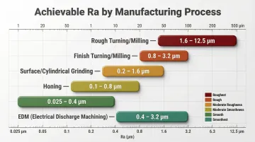
Typical Ra ranges by process:
| Manufacturing Process | Ra Range (µm) | Ra Range (µin) |
|---|---|---|
| Rough Turning/Milling | 3.2 – 12.5 | 125 – 500 |
| Finish Turning/Milling | 0.4 – 3.2 | 16 – 125 |
| Surface/Cylindrical Grinding | 0.1 – 1.6 | 4 – 63 |
| Honing | 0.1 – 0.8 | 4 – 32 |
| Lapping/Polishing | 0.025 – 0.2 | 1 – 8 |
| EDM (Electrical Discharge) | 1.6 – 12.5 | 63 – 500 |
Factors influencing surface finish:
Cutting speed, feed rate, tool nose radius, tool wear, and coolant application all directly influence the surface finish produced. Understanding these relationships lets machinists adjust parameters before measuring — not just after a nonconforming result.
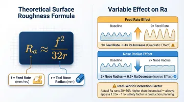
Theoretical turning roughness formula: Ra ≈ f² / (32r), where f is feed rate and r is tool nose radius.
Doubling the feed rate quadruples roughness; doubling the nose radius halves it. In practice, actual roughness runs 20–50% higher than the theoretical value due to machine vibration, built-up edge, and material tearing. Use the formula for baseline parameter selection, then apply a 1.25x to 1.5x safety factor when programming finishing passes.
Smoother isn't always better
Surface finish requirements aren't always "the smoother the better." Some applications depend on a specific roughness range to function correctly:
- Cylinder bores need a cross-hatch honed finish (0.1–0.8 µm Ra) to retain lubricating oil — too smooth causes oil film collapse and scuffing.
- Shaft surfaces with lip seals require controlled roughness to maintain sealing contact without accelerating seal wear.
- Press fits need sufficient roughness to achieve proper interference without galling during assembly.
Specifying the tightest possible finish without checking functional requirements is one of the more common — and costly — oversights in surface finish engineering.
Why Surface Finish Measurement Accuracy Depends on Calibrated Equipment
Measuring surface finish with an out-of-calibration instrument creates serious consequences: parts that are actually nonconforming may pass inspection, or good parts may be rejected—both outcomes create rework, customer returns, or production inefficiency.
The calibration process for surface finish instruments:
- Stylus condition must be checked using Type B reference specimens (narrow grooves sensitive to tip geometry)
- The instrument must be verified against certified roughness reference specimens with known Ra values traceable to NIST or equivalent international standards
- Vertical (Z-axis) amplification is checked using Type A depth standards
- Type C spacing standards verify horizontal transmission and Ra calculation accuracy
Recommended calibration intervals:
- Daily/weekly verification: Check the profilometer using a reference specimen before beginning a production run
- Formal calibration: Annual ISO 17025-accredited calibration for instruments in standard environments; reduce to 3-6 months in harsh shop-floor conditions with heavy use
Surface finish measurement is only as reliable as the entire production chain behind it—including the CNC machines generating those surfaces. For manufacturers in Portland OR and SW Washington, Sarkinen Calibrating provides NIST-traceable calibration for CNC machine tools, covering linear axis accuracy, rotary axis verification, ballbar testing, and surface plate flatness. Keeping the machines that produce your parts in calibration is as critical as keeping the instruments that measure them accurate.
Frequently Asked Questions
How is surface finish measured?
Surface finish is most commonly measured using a contact stylus profilometer that drags a fine diamond tip (typically 2 µm radius) across the surface, records vertical displacement, and calculates parameters such as Ra from the resulting profile data.
What does 3.2 surface finish mean?
3.2 refers to a roughness average (Ra) of 3.2 micrometers—a moderately smooth finish commonly specified for general precision machined surfaces such as mating faces and bearing seats. It's achievable with standard turning or milling operations.
What is the difference between surface roughness and surface finish?
"Surface roughness" specifically refers to the fine, closely spaced micro-irregularities from the machining process, while "surface finish" is a broader term that encompasses roughness, waviness, and lay together.
What is the difference between Ra and RMS surface finish?
Ra is the arithmetic average of surface height deviations, while RMS (Rq) is the square root of the mean squared deviations, making it more sensitive to large peaks or flaws. Ra is the current international standard and is more widely specified in engineering drawings today.
How often should surface finish measurement equipment be calibrated?
Most precision instruments in active production environments are calibrated at least annually. Equipment should also be recalibrated immediately after any damage, repair, or suspect measurement result, regardless of when the last calibration occurred.