Introduction
Milling machines remain one of the most versatile tools in precision manufacturing—capable of cutting, drilling, facing, and shaping metal with high accuracy. For anyone working in a machine shop or production environment, mastering milling skills is foundational to career advancement and operational success.
The basic concept of milling is straightforward. Results, however, vary dramatically depending on machine setup, tool selection, cutting parameters, and operator technique. Even experienced machinists encounter dimensional errors, poor surface finishes, or tool breakage when any one of these variables is off.
Proficient operators separate themselves from beginners through systematic preparation and the ability to diagnose problems before they create scrap.
This guide covers safe operation, pre-run setup, cutting parameters, and common troubleshooting. Whether you're training on your first machine or refining your technique, these fundamentals will help you produce accurate, repeatable results.
TL;DR
- Milling requires a structured sequence: inspect, secure the workpiece, mount the right tool, set speeds and feeds, then cut
- Speeds, feeds, depth of cut, tool selection, and calibration directly determine cut quality and dimensional accuracy
- Most beginner mistakes come from skipping prep steps or missing early signs of chatter and tool wear
- Safety is non-negotiable: PPE, proper workholding, and no measurements with the spindle running
How to Operate a Milling Machine: Step-by-Step
Step 1: Inspect and Prepare Your Work Environment
Before powering on the machine, verify that it's clean, properly lubricated, and free of leftover chips or debris from previous operations. Poor machine condition is a leading cause of inaccurate cuts. If lube is wet and black, the lubrication system may be contaminated by metal particles, requiring immediate inspection of ballscrews for wear.
Check that all machine guards are in place and the emergency stop is functional. Under OSHA 29 CFR 1910.212, milling machines require point-of-operation guarding to protect operators from rotating parts, flying chips, and sparks.
Appropriate PPE—safety glasses, non-slip closed-toe footwear, secured hair, and no loose clothing or gloves near rotating parts—must be worn before starting the machine.
Step 2: Secure the Workpiece Using Proper Workholding
The workpiece must be rigidly fastened. Any movement during the cut creates dimensional errors and poses an ejection hazard. Three primary workholding methods are used depending on workpiece geometry:
Machine Vise: Ideal for general-purpose work with square or rectangular stock. A properly torqued vise like the Kurt DX6 provides up to 7,342 lbs of clamping force at 80 ft-lbs of torque. The vise must be trammed (aligned) to the machine axes to ensure cuts are square and accurate.
T-Slot Clamps: Exert holding forces up to 150 kN and work well for multi-part fixturing or workpieces that won't fit in a vise. The cross-wedge structure locks firmly in every direction as it's tightened, eliminating measurement error from sliding.
Custom Fixtures: Purpose-built for high-volume production where exact repeatability between parts is non-negotiable. Tombstones on horizontal machining centers hold multiple parts on up to four sides.
Critical Safety Rule: Position the clamping arrangement so that cutting forces are directed onto the table surface (metal-on-metal-on-metal) and away from the cutter. Over-clamping causes elastic distortion leading to loss of accuracy, while under-clamping allows the workpiece to eject dangerously.
Step 3: Select and Mount the Cutting Tool
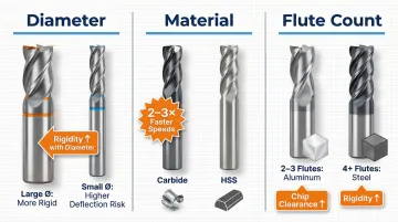
Tool selection logic depends on three factors:
- End mill diameter: Larger diameters provide more rigidity and reduce deflection
- Material: Solid carbide is more rigid than high-speed steel and can be run 2-3 times faster
- Flute count: Fewer flutes (2-3) for aluminum to maximize chip clearance; more flutes (4+) for steel to improve rigidity and surface finish
The wrong tool choice leads to tool breakage, poor surface finish, or chip packing.
Proper Tool Mounting Procedure:
- Clean the collet and tool shank thoroughly
- Snap the collet into the nut before inserting the tool
- Insert the shank depth per your holder's specifications — depth requirements vary by holder type
- Torque to spec using a torque wrench
A loosely mounted tool is one of the most dangerous milling errors. Premium ER collets and shrink-fit chucks offer runout accuracy under 3µm at 4xD. Mechanical interlocking holders go further — eliminating micro-creeping and pull-out to push tool life from 70 to 156 parts in heavy roughing.
Step 4: Set Spindle Speed and Feed Rate
Spindle speed (RPM) is determined by the cutting surface speed for the material and tool diameter. The standard formula is:
Speed (RPM) = (Surface Feet per Minute × 3.82) / Tool Diameter
Baseline Parameters for Carbide End Mills:
| Material | SFM Range | Chip Load (1/4" Dia) | Chip Load (1/2" Dia) |
|---|---|---|---|
| Aluminum (6061) | 330-400 SFM | 0.0015-0.0024 IPT | 0.0030-0.0043 IPT |
| Mild Steel (1018) | 80-115 SFM | 0.0011-0.0015 IPT | 0.0021-0.0025 IPT |
Feed rate is calculated as: Feed Rate = RPM × Chip Load × Number of Teeth
Too slow a feed causes rubbing and work hardening; too fast causes tool breakage. Use higher SFM values for radial depths less than 25% of the diameter, and lower values for radial depths greater than 25%.
Step 5: Execute the Cut and Monitor the Operation
Follow this cutting sequence:
- Position the tool clear of the workpiece
- Start the spindle
- Approach to depth
- Engage the feed (manual or power)
- Make the cut while remaining at the machine at all times
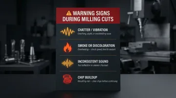
What to Watch and Listen For:
- Unusual vibration (chatter): Indicates tool overhang is too long, depth of cut is excessive, or workholding is inadequate
- Smoke or discoloration: The tool is overheating — check speed/feed settings and cutting fluid flow
- Inconsistent sound: Suggests tool deflection or uneven chip load
- Chips piling up: Leads to chip recutting and accelerates tool wear — clear them before continuing
Any of these signals means stop the cut, identify the cause, and correct it before proceeding. Catching problems early prevents scrapped parts and broken tooling.
What You Need Before Training on a Milling Machine
Preparation directly determines the quality of both training and production outcomes. Walking up to a milling machine without the right equipment, baseline knowledge, and machine verification in place leads to unsafe conditions and wasted material. Both areas — machine readiness and operator readiness — need to be confirmed before the first cycle runs.
Equipment and Machine Readiness
The machine must be in proper working order before training begins. A machine running out of spec looks operational but produces parts outside tolerance. Verify these four systems before proceeding:
- Axis movement confirmed across full travel
- DRO (digital readout) functioning and zeroed correctly
- Lubrication system operational
- Spindle calibrated and within spec
New machines are a particular concern — transportation can introduce alignment errors or hidden damage that isn't visible during a basic inspection. Professional calibration using NIST-traceable laser interferometry verifies a machine is actually performing to its promised specifications, not just appearing to. For shops in Portland OR and SW Washington, Sarkinen Calibrating provides this verification with faster turnaround than out-of-area providers.
Skill and Safety Readiness
Trainees should have completed basic shop safety orientation before touching the machine, covering:
- PPE requirements (safety glasses, substantial non-slip closed-toe footwear, secured hair)
- Chip removal procedures (brush only, never hands)
- Emergency stop location
- The rule that no measurements are taken while the spindle is rotating
- Glove prohibition near rotating spindles (OSHA explicitly prohibits gloves near rotating machinery due to entanglement risk)
Operators should understand the machine's anatomy—table, saddle, knee, column, head, quill, and spindle—before attempting to run a cycle. With this foundation in place, trainees can begin operating with purpose rather than guesswork.
Key Parameters That Affect Milling Results
Outcomes in milling are determined by how well the operator controls a handful of interdependent variables. Changing one without adjusting the others throws off the entire cut. This is the technical core of developing real milling skill.
Depth of Cut
Axial depth (how far the tool plunges) and radial depth (stepover) must be balanced against tool diameter and material hardness. Aggressive depths without adjusting feed rate lead to tool deflection and dimensional inaccuracy.
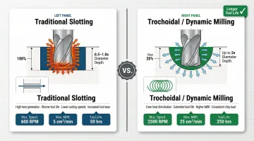
Traditional Slotting: Radial depth of 100% (1xD), axial depth of 0.5x to 1.0x diameter
Trochoidal/Dynamic Milling: Radial depth of maximum 20% of diameter, axial depth up to 2x diameter
Trochoidal milling uses a small radial depth of cut with massive axial depths, reducing heat and harmonic vibration while maximizing material removal rates. The controlled arc of engagement generates low cutting forces and spreads heat uniformly across the cutting edge, leading to longer tool life.
Spindle Speed (RPM)
Running too fast generates excessive heat and tool wear; too slow causes rubbing instead of cutting. Surface footage (SFM) and tool diameter determine the correct RPM using the formula provided earlier.
Feed Rate
Chip load is the key concept—each flute of the cutter needs to remove a specific amount of material per revolution. Matching feed rate to spindle speed and flute count prevents both rubbing (underfeeding) and overloading (overfeeding).
Tool Condition and Selection
Dull or chipped tools require more cutting force, generate more heat, and produce worse surface finishes. Visual signs of a worn tool include:
- Corner chipping or rounding
- Flank wear (shiny band on the cutting edge)
- Built-up edge (material welding to the tool)
- Discoloration from heat
Running dull or mismatched cutters is one of the fastest ways to introduce dimensional variation and scrap.
Machine Calibration and Accuracy
Even perfect operator technique cannot compensate for a machine that is out of calibration. Axis backlash, spindle runout, and geometric errors accumulate into dimensional defects.
Pseudo-static geometric errors (translational and rotational errors) and thermal errors impact the calibrated performance of the machine. When a machine tool goes out of calibration for machining, it simultaneously goes out of calibration for measurement.
Regular calibration verified to NIST-traceable standards separates machines that hold tolerance from ones that accumulate hidden errors until a batch comes out as scrap. Ballbar testing provides a comprehensive snapshot of machine health, identifying backlash, servo mismatch, axis reversal errors, and squareness problems in a single diagnostic run.
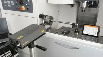
For Portland OR and SW Washington shops, Sarkinen Calibrating uses Renishaw's QC20-W Ballbar system to troubleshoot accuracy problems, validate recent service work, and support maintenance planning before dimensional errors reach the part.
Common Milling Machine Mistakes to Avoid
Skipping Pre-Operation Checks
Many operators skip inspection and workholding verification steps when under production pressure. This shortcut leads to scrapped parts, broken tools, or dangerous workpiece ejections. Skipping these checks rarely saves time — it just moves the cost downstream, where it's always higher.
Incorrect Parameter Selection
Using the same speeds and feeds across different materials or tool sizes is one of the most common beginner errors. Recognize when parameters are wrong by watching for:
- Excessive heat or discoloration
- Chatter or vibration
- Poor surface finish
- Rapid tool wear
Calculate or reference parameters before each job. Consulting manufacturer data or machining handbooks takes minutes and prevents costly mistakes.
Ignoring Early Warning Signs During the Cut
During a cut, these signals demand attention — not patience:
- Chatter or vibration
- Unusual sounds
- Discoloration on the workpiece or tool
Stopping to diagnose the cause is always less costly than running through a tool or scrapping a part.
Troubleshooting Common Milling Problems
Even well-prepared operators hit snags. The four problems below — chatter, poor surface finish, dimensional inaccuracy, and tool breakage — cover most of what you'll encounter, along with the likely causes and specific fixes for each.
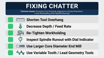
Chatter (Vibration During Cut)
Common causes: tool overhang too long, excessive depth of cut, worn spindle bearings, or a workpiece that isn't properly secured.
- Shorten tool overhang to the minimum usable length
- Decrease depth of cut or feed rate
- Re-tighten workholding and verify rigidity
- Inspect the spindle for runout using a dial indicator
- Choose end mills with a larger core diameter for better stability
- Use tools with variable tooth spacing and variable-lead geometry to suppress harmonic vibrations
Poor Surface Finish
Common causes: dull tool, incorrect feed rate, insufficient cutting fluid, or a workpiece with flex in the setup.
- Inspect and replace the cutting tool if worn
- Recalculate chip load for the specific material
- Apply the right cutting fluid — for aluminum, products like Castrol Alusol prevent chip welding; for steel, use high-performance soluble oils
- Verify the workpiece is clamped without any flex
Dimensional Inaccuracy (Parts Out of Tolerance)
Common causes: axis backlash, thermal growth in the spindle, tool deflection under load, or a machine that has drifted out of calibration.
- Switch between climb and conventional milling to minimize backlash effects
- Let the machine reach thermal equilibrium before making precision cuts
- Reduce depth and width of cut to lower tool deflection
- If inaccuracy persists across multiple setups, schedule a machine calibration check — persistent dimensional drift often points to a machine accuracy issue rather than an operator error
Tool Breakage
Common causes: feed rate too aggressive for the tool diameter or material, poor chip evacuation, direct plunging, or a worn tool pushed past its useful life.
- Reduce feed rate and depth of cut
- Clear chips more frequently, especially in deep pockets
- Use a ramping or helical entry instead of a direct plunge
- Start every job with a sharp tool — running a dull tool to failure is rarely worth the time saved
Frequently Asked Questions
What is the golden rule of milling?
The golden rule of milling is to keep the cutting tool sharp, properly secured, and matched to the correct speed and feed for the material. No operation should begin without verifying that the workpiece is rigidly clamped and that all safety guards are in place.
How to become a milling machine operator?
Start with a formal apprenticeship or vocational program, then build hands-on machine time under supervision. From there, progression means learning to read engineering drawings, program CNC equipment, and sharpen parameter judgment through real shop experience.
How much does a CNC course cost?
Costs range from a few hundred dollars for short certificate programs to a few thousand for full community college courses. Employer-sponsored apprenticeships often come at no cost to the trainee. Research local options for current pricing.
What's the difference between CNC milling and manual milling?
Manual milling requires the operator to control every axis movement by hand using handwheels, giving direct control over the cutting process. CNC milling uses programmed instructions (G-code) to automate movements with greater repeatability and precision. Manual skills remain foundational for understanding what the CNC machine is doing.
How long does it take to learn milling machine operation?
Basic competency—safe setup and simple cuts—can be reached in weeks of consistent practice. Full proficiency in parameter selection, troubleshooting, and precision work takes months to years, depending on the complexity of work and how frequently you're at the machine.
What PPE is required for operating a milling machine?
Required PPE includes safety glasses or a face shield, non-slip closed-toe footwear, secured hair, and no loose clothing or dangling jewelry. Gloves must never be worn while the machine is running—OSHA explicitly prohibits them near rotating equipment due to entanglement risk.