Introduction
Running a CNC machine that's even slightly out of spec is expensive. Small deviations compound quickly—what begins as a tenth of a millimeter of backlash or a fraction of a degree of squareness error becomes scrap parts, rework cycles, missed tolerances, and unplanned downtime. The costs add up fast: automotive manufacturers lose $2.3 million per hour during unplanned outages, while general manufacturing facilities face $125,000 to $260,000 per hour. Treating CNC testing as a core operational discipline—rather than an afterthought—is what separates facilities that catch problems early from those that absorb them as scrap costs.
This guide walks through the techniques manufacturers rely on to verify machine accuracy—ballbar testing, axis calibration, squareness checks, and more—along with the tools and practical steps to catch deviations before they reach a finished part.
TL;DR
- CNC testing verifies axes, positioning, geometry, and drives perform within acceptable tolerances
- Core tests include cutting geometric shapes, checking backlash, and running repeatability patterns
- Tools range from dial indicators to ballbar systems and laser interferometers
- Catching drift early prevents defects and builds a documented record of machine health over time
- NIST-traceable professional calibration reaches accuracy levels that in-house tools cannot match
What Is CNC Testing and Why It Matters
CNC testing is the systematic process of verifying that a machine's axes, positioning, geometry, and drive systems perform within designed tolerances. It covers both accuracy (hitting the right target) and repeatability (hitting it consistently across multiple cycles).
Accuracy vs. Repeatability: Why Both Matter
These terms are frequently confused, but they measure different things:
- Accuracy — how close the machine gets to the intended target position
- Repeatability — how consistently it returns to that same position across multiple cycles
A machine can be repeatable but inaccurate (consistently hitting the wrong spot), or accurate on average but inconsistent (scattered around the target). Both must be evaluated separately because each reveals different mechanical problems.
Four Critical Scenarios Where CNC Testing Matters
- Verify new machines meet promised specs before warranties expire — shipping and installation introduce alignment errors that factory acceptance tests don't catch
- Catch ballscrew degradation, guideway wear, and servo drift before they produce defective parts
- Reduce scrap and rework costs by identifying dimensional errors early, before they compound into wasted material and extended lead times
- Provide customers with NIST-traceable calibration records as documented proof of machine capability
Key CNC Testing Techniques and Tools
CNC testing divides into two categories: geometric performance tests that reveal how well a machine executes real cuts, and precision measurement instruments that quantify the results.
Geometric Accuracy Tests
Standard geometric test cuts reveal machine performance under real operating conditions. Run these at representative speeds in materials similar to production stock; soft wax or foam will mask the problems you're trying to find.
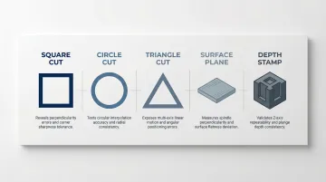
Five standard cuts cover the most common failure modes:
- Square test — axis perpendicularity and corner sharpness
- Circle test — circular interpolation quality and radial consistency
- Triangle test — simultaneous multi-axis motion and interpolator quality
- Surface planing test — spindle perpendicularity to the table
- Stamp/cube milling test — Z-axis perpendicularity across depth layers
. In ballscrew-driven machines, readings above 0.03mm typically warrant drive system inspection before the error compounds into scrap.
Repeat drilling test: Drill the same hole pattern multiple times without moving the workpiece. Examine whether holes align. This exposes inconsistencies that geometric cuts alone won't catch, such as random positioning errors caused by electrical noise or inconsistent servo response.
Precision Measurement Instruments
Digital calipers and dial indicators: Basic in-shop checks for geometric test cuts and backlash measurement. Accurate to 0.01-0.02mm, sufficient for general monitoring but not precision verification.
Ballbar systems: The Renishaw QC20-W ballbar detects servo backlash, gain mismatches, and circular deviation quickly. Resolution of 0.1 µm and measurement accuracy of ±(0.7 + 0.3% L) µm at 20°C. The ballbar measures variations in radius as the machine interpolates a circular path, isolating dynamic and geometric errors during simultaneous multi-axis motion.
Laser interferometers: Measure positioning accuracy, pitch error, and linear deviation with high precision. The Renishaw XL-80 laser interferometer delivers 0.001 µm (1 nm) resolution and ±0.5 ppm linear measurement accuracy at 95% confidence. It covers linear positioning, pitch, yaw, straightness, squareness, and flatness in a single system.
NIST-traceable professional calibration: Achieves measurement accuracy to 1 part per million, which meets the 10:1 accuracy ratio required for valid calibration. Uncompensated environmental factors (air temperature, pressure, humidity) can introduce 20-30 ppm of measurement uncertainty, exceeding the machine errors being measured. Professional systems use active environmental compensators to maintain ±0.5 ppm accuracy across fluctuating shop floor conditions.
How to Run a CNC Accuracy Test: Step-by-Step
Each step below addresses a specific failure point where real-world tests go wrong—from skipping thermal prep to documenting results for trend tracking. Follow the sequence in order; shortcuts at any stage can produce misleading data.
Step 1 – Prepare the Machine and Environment
Stabilize shop temperature before testing. Thermal drift is a leading cause of measurement error. ISO 1:2022 fixes the standard reference temperature at 20°C for geometrical and dimensional properties. If testing occurs outside this temperature, apply Nominal Differential Expansion (NDE) correction —a calculation that accounts for how different materials expand at different rates. Allow the machine and measuring instruments to reach thermal stability—preferably overnight—protected from drafts and sunlight.
Clean and inspect the machine:
- Clean guideways and spindles of chips and coolant residue
- Verify lubrication system is functioning and oil levels are correct
- Secure all fasteners—loose mounting bolts introduce positioning errors
- Confirm E-stop works and power supplies deliver correct voltages
- Listen for unusual noise from servo or stepper motors during warmup
Skipping this step is the most common reason test results are misleading. A machine with contaminated guideways or low lubrication will test poorly even if mechanically sound.
Step 2 – Cut and Measure Geometry Test Shapes
Cut square, circle, triangle, and ellipse test shapes at representative feed rates. Measure results with calipers at multiple orientations:
- Check square corners for sharpness and rounding
- Measure diagonal lengths—they should match within 0.02mm
- Examine cut surfaces for waves or vibration artifacts
- Test in multiple areas of the table, not just the center
Machine errors often vary by position. A machine that tests well in the center may show significant errors at the table extremes where structural deflection is greatest. Those positional differences become the focus of the next step.
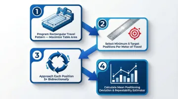
Step 3 – Test Positioning Accuracy and Repeatability
Program the machine to travel a large rectangular pattern (maximizing table area), return to home position, and verify the return point matches the start point after multiple cycles. ISO 230-2:2014 dictates the standard test cycle: select minimum five target positions per meter of travel, approach each position five times in each direction (bidirectional), and calculate mean positioning deviation and repeatability estimator.
Run the repeat drilling pattern test. Check return-to-origin accuracy by measuring zero-point variance across multiple home cycles. Inconsistent homing indicates encoder problems or mechanical play in the home switch assembly.
Step 4 – Check for Backlash and Drive Issues
Jog each axis through its full range using a dial indicator to measure any play. Listen for unusual noise from servo or stepper motors:
- Constant noise on steppers typically indicates missed steps
- Servo oscillation signals tuning issues—the servo is hunting around the target position
- Grinding or scraping sounds indicate worn guideways or ballscrews
Check that direction reversals are clean without hesitation or overshoot. Mount the dial indicator, jog forward, zero the indicator, reverse direction, and measure the gap before motion starts.
Step 5 – Analyze Results Against Acceptable Tolerances
Compare measured deviations against tolerance standards appropriate for the machine type. ISO 10791-1:2015 establishes tolerances for milling machines:
| Axis Length | Straightness Tolerance |
|---|---|
| ≤ 500 mm | 0.010 mm |
| 500-800 mm | 0.015 mm |
| 800-1250 mm | 0.020 mm |
| 1250-2000 mm | 0.025 mm |
Identify whether errors are systematic (consistent pattern suggesting axis or drive issue) or random (suggesting environmental or electrical noise problems). Systematic errors can often be corrected through controller compensation. Random errors indicate deeper mechanical or electrical problems.
Step 6 – Act on Findings and Close the Loop
For minor, consistent positional errors: Apply pitch error compensation or backlash compensation in the controller. Modern CNC controllers (Fanuc, Siemens) use software compensation to correct known mechanical deviations. Pitch error compensation accounts for minute mechanical errors in the ballscrew, rack and pinion, or linear scale along each axis.
For errors beyond in-house correction capability: Schedule professional calibration. Controller compensation cannot correct structural geometric errors (like squareness), dynamic thermal drift, or non-repeatable mechanical play.
Document all test results with timestamps. Build a trend record that reveals gradual drift over time. A documented history of gradual drift is far more actionable than a single out-of-tolerance reading because it shows the rate of change and helps predict when intervention is needed.
CNC Testing Best Practices
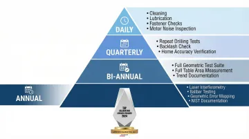
Establish a tiered testing schedule that balances thoroughness with operational efficiency:
Daily simplified checks:
- Clean guideways and remove chip buildup
- Verify lubrication system operation
- Check for loose fasteners
- Listen for unusual motor noise
Quarterly repeatability tests:
- Run repeat drilling patterns
- Check backlash with dial indicators
- Verify return-to-home accuracy
Bi-annual full geometric accuracy tests:
- Cut complete test piece suite (square, circle, triangle)
- Measure across full table area
- Document results for trend analysis
Annual professional NIST-traceable calibration:
- Laser interferometry for linear positioning
- Ballbar testing for dynamic performance
- Full geometric error mapping
- Formal documentation for quality management systems
This tiered approach pays off in measurable ways. According to a 2024 Siemens report, implementing predictive maintenance can yield a 50% reduction in unplanned machine downtime and an 85% improvement in downtime forecasting accuracy.
Run a full test suite on a new machine before the warranty expires. Verify it meets manufacturer specifications under real operating conditions — not just the acceptance test conditions from the factory. Shipping and installation introduce alignment errors that factory testing won't catch.
Log every test result in a maintenance record, not just failures. A documented history of gradual drift is far more actionable than a single out-of-tolerance reading. Track positioning deviation, backlash measurements, and geometric test results over time. That trend data tells you when professional calibration is coming due — before a tolerance violation tells you first.
How Sarkinen Calibrating Can Help
Once you've worked through in-house CNC testing, professional calibration fills the gaps that shop-grade tools can't reach. Sarkinen Calibrating works with machine shops and production facilities across Portland, OR and SW Washington to verify and maintain the accuracy that in-house checks can flag but rarely quantify.
Using Renishaw laser interferometry, measurements are accurate to 1 part per million — one millionth of an inch per inch of travel. That's well beyond the 10:1 ratio required for proper calibration, and far beyond what shop-grade calipers and dial indicators can verify.
Comprehensive calibration capabilities:
- New machine acceptance testing to verify specifications while under warranty
- Ongoing predictive calibration that catches drift before it causes defects
- Ballbar testing with the Renishaw QC20-W for rapid machine health assessment
- Linear axis calibration measuring positioning accuracy, repeatability, straightness, and squareness
- Rotary axis calibration for multi-axis machining centers
Founder Larry started as a machine operator before building Sarkinen Calibrating, which shapes how the service operates. Calibration here isn't treated as routine maintenance — it's approached as a production problem: how do you keep machines running accurately with minimal disruption to the schedule? That operator-first perspective drives a focus on highly predictable outcomes rather than reactive fixes.
For Portland OR and SW Washington facilities, local service means faster response times than out-of-area providers — critical when a calibration issue is holding up production. Call (360) 907-3058 to schedule.
Frequently Asked Questions
What does CNC stand for?
CNC stands for Computer Numerical Control. It's a system where a machine follows pre-programmed numeric instructions to control movement, speed, and position—rather than relying on a machinist to guide it manually.
What is the difference between CNC accuracy and repeatability?
Accuracy means how close the machine gets to the intended target position. Repeatability means how consistently it returns to that same position across multiple cycles. Both must be tested separately because a machine can be inaccurate but repeatable, or accurate on average but inconsistent.
How often should CNC machines be tested and calibrated?
A tiered schedule works best:
- Daily: Cleaning, lubrication, and fastener checks
- Quarterly: Repeatability testing
- Bi-annually: Full accuracy testing
- Annually: Professional NIST-traceable calibration
High-production or tight-tolerance environments may need more frequent cycles.
What tools do I need to test CNC machine accuracy at my shop?
Basic: Digital calipers for geometric test cuts, a dial indicator for backlash testing, and repeatability drilling programs.
Advanced: Ballbar systems (Renishaw QC20-W) or laser interferometers (Renishaw XL-80) for precision verification.
How do I test a CNC machine for backlash?
Mount a dial indicator against the axis, jog the axis in one direction and zero the indicator, then reverse direction and measure any movement before the axis starts translating. That gap is the backlash—typically caused by worn ballscrews or loose couplings.
When should I call a professional calibration service instead of testing in-house?
Call a professional when deviations exceed your controller's compensation range, when NIST-traceable documentation is required for customers or regulatory purposes, when verifying new machines against warranty specs, or when in-house tests show drift but the source cannot be identified.